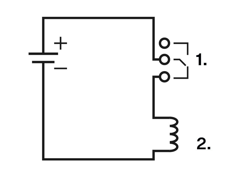
Relay Terminal Wiring Diagrams
It is possible to connect a device to the 2N IP Force relay terminals to be controlled by this relay, e.g. an electric/electromechanical door lock.
The elements are designated as follows in the diagrams below:
Device relay
Controlled device
Figure 1. Wiring diagram for closing the electric circuit of the controlled device
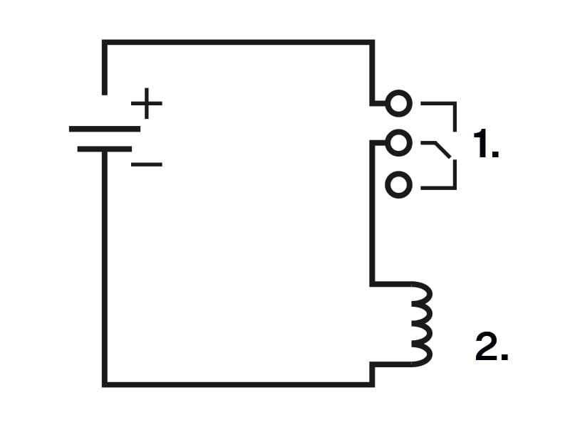
Figure 2. Wiring diagram for opening the electric circuit of the controlled device