Module Specifications
Security Relay
The Security Relay (9159010, 01386-001) is used for enhancing security between 2N IP Solo and the connected electric lock. The Security Relay significantly enhances security of the connected electric lock by preventing unlocking due to device tampering.
Specification
Passive switch | NO/NC contact, up to 30 V / 1 A AC/DC |
Switched output |
|
Dimensions | 66.5 × 32.5 × 20.5 mm |
Weight | 24 g |
Connectors and Installation
The Security Relay is installed between the device (outside the secured area) and the electric lock (inside the secured area). The Security Relay includes a relay that can only be activated if a valid access card/code is detected on the unit.
The Security Relay is installed on a two-wire cable between the device and the electric lock inside the area to be secured (typically behind the door). The Security Relay is powered and controlled via this two-wire cable and can thus be added to an existing installation. Thanks to its compact dimensions, the device can be installed into a standard mounting box.
The Security Relay is designed with holes for surface anchoring. It is recommended that a screw of the diameter of 3 mm with a lens head of the diameter of 6 mm is used. Using a countersunk head may cause irreversible damage to the plastic cover!
 |
|
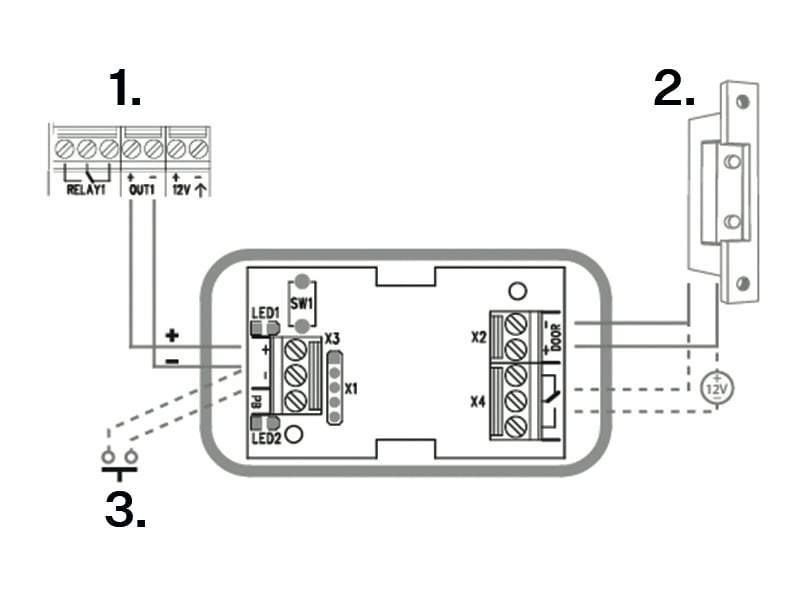
Connect the Security Relay to the access unit as follows:
To the Active output
Connect the electric lock to the Security Relay as follows:
to the switched output
to the passive output in series with the external power supply
The Security Relay also supports the Departure button connected to the ‘PB’ and ‘– 2N IP intercom’ terminals. Once the Departure button is pressed, the output is activated for 5 seconds.
Status Signaling
Green LED | Red LED | State |
|---|---|---|
flashing | off | Operational mode |
on | off | Activated output |
flashing | flashing | Programming mode – waiting for initialization |
on | flashing | Error – wrong code |
Configuration
Connect the Security Relay to the properly set Security output of the device. Refer to the Configuration Manual for details. Make sure that one LED at least is on or flashing.
Press and hold the Relay RESET button for 5 seconds to switch the device in the programming mode (red and green LEDs flashing).
Activate the output switch using the keypad, telephone, etc. The first code sent from the device will be stored in the memory and considered valid. After code initialization, the Security Relay will pass into the operational mode (green LED flashing).
Caution
Having reset the factory defaults on a device with firmware 2.18 or higher, remember to reprogram Security Relay using the instructions above.