This document summarises brief steps for an installation of a new purchased 2N gateway. It consists of all necessary details needed for a successful setup of your HW. After reading this guide you will be able to configure the gateway to process calls to/from the GSM network.
The FAQ applies for following GSM/UMTS gateways:
-
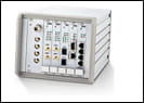
2N BlueTower (2 to 8 GSM/UMTS channels)
-
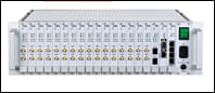
2N StarGate (2 to 32 GSM/UMTS channels)
Product basics:
-
Up to 8 (2N BlueTower) or 30 (2N StarGate) simultaneous calls from/to any interface of the gateway
-
Up to 8 (2N BlueTower) or 32 (2N StarGate) GSM/UMTS modules with 1, 4 or 8 SIM cards per one GSM/UMTS module
-
Optional support of the SMS messaging over Email and SMPP protocols (additionally licensed features)
-
Optional support of the SNMP network monitoring protocol (additionally licensed feature)
1) Hardware setup
-
Gateway - unpack the chassis from the shipping box and install it on an appropriately dry and climatised location.
-
Cables
-
Power supply cable - use attached power supply cable or a 3 pins power supply cord (designed for 100–240V AC/50-60Hz) with an independent grounding wire. Please make sure the gateway uses the same grounding source as the locally connected PBX.
-
Ethernet cable - use attached Ethernet cable or a standardised 100BASE FastEthernet cable. Connect the CPU board and one port of the VoIP board to your local network switch.
If you would like to change the default IP address of the CPU (192.168.1.2) to a different one from your LAN IP addresses range, connect your PC to the CPU directly over an Ethernet cable first and change it before connecting to the LAN (see the User guide or steps below). -
ISDN cable - strictly use attached ISDN cable
-
-
Antenna
-
Indoor antenna - connect an independent antenna to each GSM/UMTS module
-
YAGI antenna - connect each GSM/UMTS module to the splitter using the short interconnection cables with SMA connectors and also do not forget to interconnect the splitter with an outdoor YAGI antenna using the coaxial cable with N connectors.
-
-
SIM cards
-
Insert SIMs with disabled PIN code request or with the same PIN code set for all inserted SIMs
-
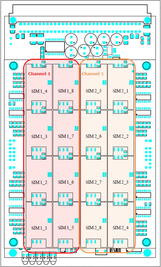
Insert one SIM card per each GSM/UMTS module at least (see the SIM positions layout for different board types below)
1 SIM per module
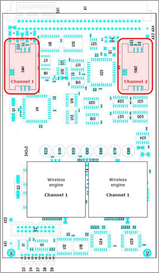
4 SIMs per module
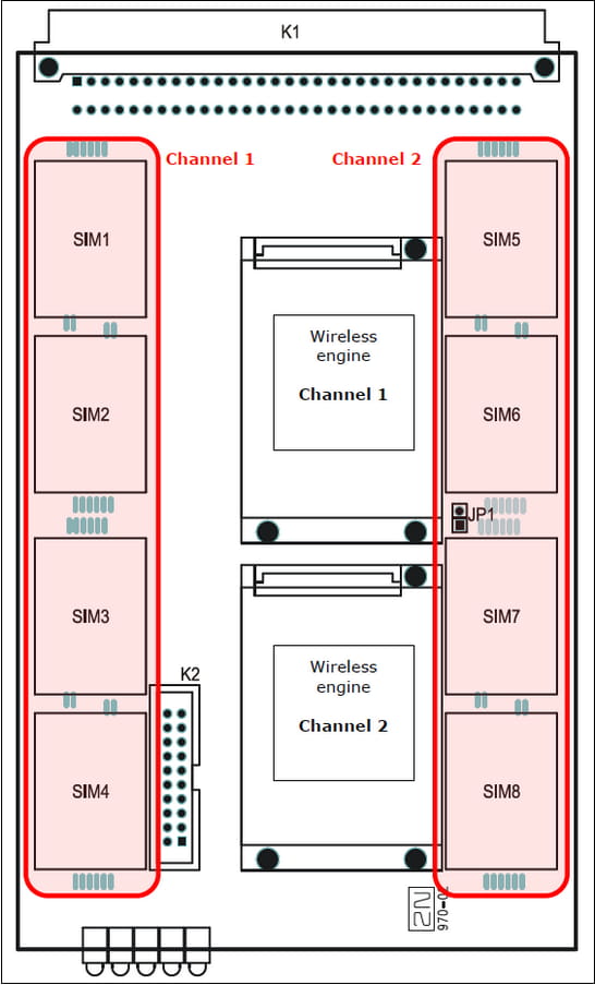
8 SIMs per module
-
If you would like to insert more than one SIM per module, it is high recommended to use SIM cards of the same type
(operator, prepaid/postpaid etc.) in the same GSM/UMTS module!!!
-
2) Product configuration
-
Configuration interface
-
Web - the gateway can be easily configured over a graphical web interface (English /Spanish /Czech language localisations). The GUI is available on the default web port of the gateway's IP address (192.168.1.2 in factory default) using any web browser.
-
Serial port - it is very suitable as a backup configuration interface (when for ex. Ethernet unreachable or not available). The configuration is possible over a console terminal, the communication speed of the serial interface is 57.600bps.
-
-
Basic configuration
-
Time and date
-
CDRs
-
ISDN/VoIP
-
-
Calls routing
-
Routing logic
-
Outgoing calls
-
Incoming calls
-
|
Factory default values IP address of the CPU – 192.168.1.2; mask 255.255.255.0, default gateway 192.168.1.1 IP address of the VoIP board – 0.0.0.0, you need to manually set some to avoid one way audio issue! ; mask and the default gateway are shared with the CPU (255.255.255.0, 192.168.1.1) SIP protocol - port 5060, UDP protocol (TCP protocol support has to be enabled in VoIP parameters) Username/password – Admin/2n Transmission rate of the serial port – 57.600bps |
3) Optional add-ons
SMS messaging
2N GSM/UMTS gateways can be used for calls and text messaging at the same time. If you would like to use your gateway also for SMS sending, take a look at the SMS messages - How to send and receive messages? - SMS gateway integration
BTS Lock
Random or locked usage of surrounded BTSs can se set over the web interface in the menu Utils - BTS lock (see picture below).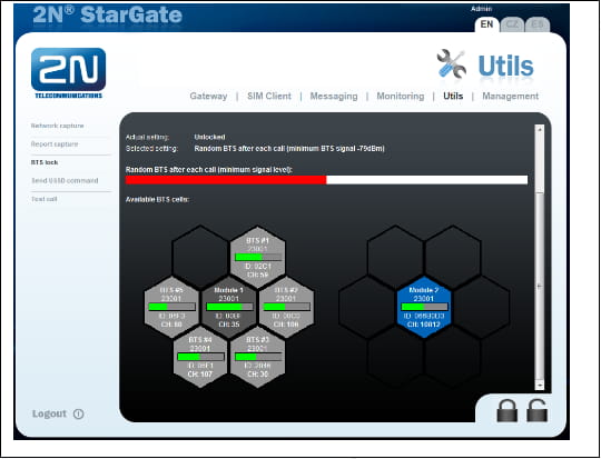
SNMP monitoring
Online IP monitoring of the GW's status.
Frequently asked questions corner:
-
There are 32 GSM modules in my 2N® StarGate gateway. Why can I make only 30 simultaneous calls at once?
The gateway is designed to handle 30 calls at once. Additional 2 GSM modules can be used for ex. as a backup or for SMS messaging. -
I have inserted 4 SIM cards for each GSM module. Why can I make only one call per module and not four calls?
One GSM module can actively use only one SIM card at the moment, same way as for ex. your mobile phone. The other SIMs can be switched based on predefined time or usage conditions. -
Is there any difference between the GSM and UMTS boards? Does the UMTS board support GSM networks?
The GSM board support standard legacy 2G networks running on 850/900/1800/1900 MHz.
The UMTS board supports all GSM network bands and the 3G networks running on 800/850/900/2100 MHz. -
Is there any difference between the YAGI and indoor antennas?
The YAGI is a directional antenna you can easier point to for ex. some specific BTS.
The indoor antenna is omnidirectional with no specific orientation.