Module Specifications
125 kHz RFID Card Reader Module
The 125 kHz RFID card reader module (91550941, 02140-001) is used for reading RFID card IDs in the 125 kHz bandwidth.
To accelerate access card reading, we recommend that the used card types are only selected in the module settings.
Caution
We recommend that the M-Bus and LAN cable are not crossed but carried separately through separate bushings to increase the reading distance of this reader & touch display installation.
Features
The module contains two bus connectors for the 2N IP Style bus.
These two connectors are fully interchangeable and can be used either as inputs from the main unit or outputs to other modules.
If this module is the last one on the bus, one of the connectors remains unconnected.
The module package includes a 220 mm long interconnecting cable.
13.56 MHz, NFC RFID Card Reader Module
The 13.56 MHz RFID card reader (91550942, 02139-001) is used for reading RFID card IDs in the 13.56 kHz bandwidth.
To accelerate access card reading, we recommend that the used card types are only selected in the module settings.
Features
The module contains two bus connectors for the 2N IP Style bus.
These two connectors are fully interchangeable and can be used either as inputs from the main unit or outputs to other modules.
If this module is the last one on the bus, one of the connectors remains unconnected.
The module package includes a 220 mm long interconnecting cable.
Secured 13.56 MHz NFC RFID Card Reader Module
The 13.56 MHz RFID card reader (91550942-S/9155086, 02141-001/01712-001) is used for reading secured RFID card IDs in the 13.56 MHz bandwidth.
Features
The module contains two bus connectors for the 2N IP Style bus.
These two connectors are fully interchangeable and can be used either as inputs from the main unit or outputs to other modules.
If this module is the last one on the bus, one of the connectors remains unconnected.
The module package includes a 220 mm long interconnecting cable.
Biometric Fingerprint Reader Module
The Biometric fingerprint reader module (9155045, 01276-001) is used for verification of human fingers for access control and 2N/third party equipment control.
Warning
The fingerprint reader may not be installed on places exposed to direct sunlight. If exposed to direct sunlight, the device may report errors.
Features
The module contains two bus connectors for the 2N IP Style bus.
These two connectors are fully interchangeable and can be used either as inputs from the main unit or outputs to other modules.
If this module is the last one on the bus, one of the connectors remains unconnected.
The module package includes a 220 mm long interconnecting cable.
Important module properties:
FBI PIV and Mobile ID certification – FAP20
durable glass touch surface
rejection of spoof fingerprints
operating temperature range: −20 to 55 ºC
0–90 % relative humidity, noncondensing
Caution
A higher moisture may deteriorate the finger papillary line scanning. You are advised to dry your finger and the reader scanning surface for successful authentication.
Fingerprint scanning may be more difficult for seniors whose finger papillary lines are not so distinctive (skin elasticity drops with age and a higher scanning pressure may lead to fingerprint blurring).
5-Button Module
The 5-Button module (9155035, 01258-001) is used for selected Automation functions. Refer to 2N.com for the printing template.
The buttons are backlit and can include nametags.
Features
The module contains two bus connectors for the 2N IP Style bus.
These two connectors are fully interchangeable and can be used either as inputs from the main unit or outputs to other modules.
If this module is the last one on the bus, one of the connectors remains unconnected.
The module package includes a 220 mm long interconnecting cable.
Specification
Nametag dimensions (W x H) |
|
I/O Module
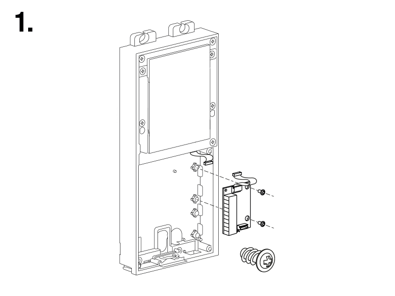
The I/O module (9155034, 01257-001) is used for extending the inputs and outputs.
Features
The module contains two bus connectors for the 2N IP Style bus.
These two connectors are fully interchangeable and can be used either as inputs from the main unit or outputs to other modules.
If this module is the last one on the bus, one of the connectors remains unconnected.
The module package includes a 80 mm long interconnecting cable.
The inputs / outputs are addressed as follows: <module_name>.<input/output_name>, e.g. “module5.relay1”. Configure the module name in the Module Name parameter in .
Connectors and Installation
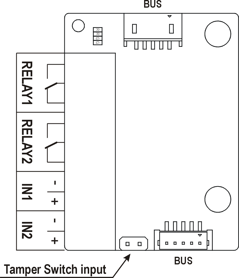
RELAY1/2 | RELAY1/2 terminals with accessible 30 V / 1 A AC/DC NO/NC contact |
IN1/2 | IN1/2 terminals for input in passive / active mode (−30 V to +30 V DC)
|
TAMPER | Tamper Switch (9155038, 01260-001) input |
The module is installed under another module, i.e. needs no separate position.
 |  |
Wiegand Module
The Wiegand module (9155037, 01259-001) is used for connecting an external Wiegand device (RFID card reader, fingerprint/biometric data scanner) and/or connecting 2N IP Style to an external security exchange.
Features
The module contains two bus connectors for the 2N IP Style bus.
These two connectors are fully interchangeable and can be used either as inputs from the main unit or outputs to other modules.
If this module is the last one on the bus, one of the connectors remains unconnected.
The module package includes a 80 mm long interconnecting cable.
Configure the module name in the Module Name parameter in .
LED IN is addressed as follows: <module_name>.<input1>, e.g. “module2.input1”.
The Tamper input is addressed as follows: <module_name>.<tamper>, e.g. “module2.tamper”.
LED OUT (negated) is addressed as follows: <module_name>.<output1>, e.g. “module2.output1”.
Specification
Current | 5 mA |
Input resistance | 680 Ω |
Pulse length | 50 μs |
Inter-pulse interval | approx. 2 ms |
Connectors and Installation
All the inputs and outputs are galvanically isolated from the device with the insulation strength of 500 V DC. It is necessary to feed +UIN on Wiegand W0OUT from the Control Panel.
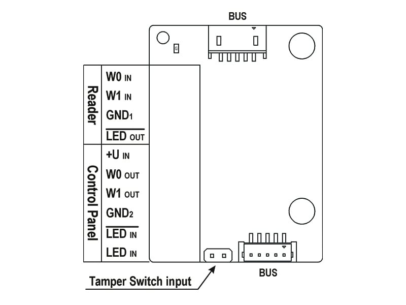
Reader helps connect an external Wiegand-supporting reader. The reader sends the device card ID.
The Control Panel is used for connection to the security PBX / access system to which the device sends the card ID information.
The module contains two BUS connectors for device bus connection. These two connectors are fully interchangeable and can be used either as inputs from the main unit or outputs to other modules.
Reader | W0IN, W1IN, GND1 | Isolated 2-wire WIEGAND IN |
LEDOUT | Isolated open LED OUT switched against GND1 (up to 24 V / 50 mA) | |
Control Panel | +UIN | +UIN (5 to 15 V DC) for WIEGAND OUT power supply |
W0OUT, W1OUT, GND2 | Isolated 2-wire WIEGAND OUT | |
LEDIN (negated) | Isolated input for open LED IN, input activated by GND2 connection | |
LEDIN | Isolated input for open LED IN, input activated after +U connection | |
G | +UIN WIEGAND OUT active supply LED indicator | |
TAMPER | Tamper Switch (9155038, 01260-001) input |
The module is installed under another module, i.e. needs no separate position.
| |
Figure 1. Recommended Wiegand bus wiring diagram, 2N device as a receiver. 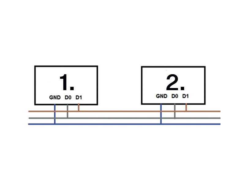 |
|
Figure 2. Recommended Wiegand bus wiring diagram, 2N device as a transmitter. |
|
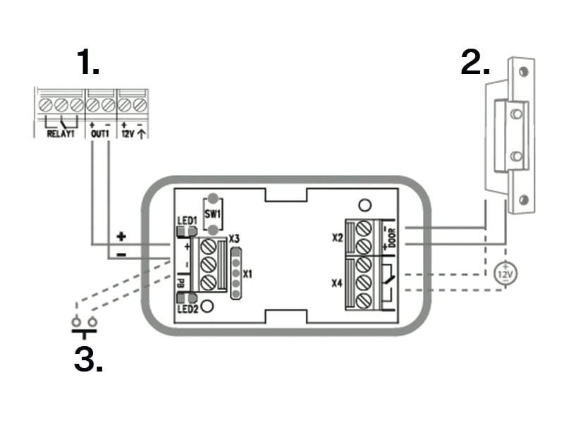
Figure 3. Recommended reader & OC output wiring diagram 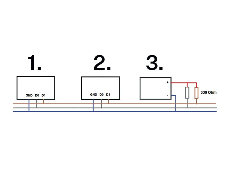 |
|
Security Relay
The Security Relay (9159010, 01386-001) is used for enhancing security between 2N IP Style and the connected electric lock. The Security Relay significantly enhances security of the connected electric lock by preventing unlocking due to device tampering.
Specification
Passive switch | NO/NC contact, up to 30 V / 1 A AC/DC |
Switched output |
|
Dimensions | 66.5 × 32.5 × 20.5 mm |
Weight | 24 g |
Connectors and Installation
The Security Relay is installed between the device (outside the secured area) and the electric lock (inside the secured area). The Security Relay includes a relay that can only be activated if a valid access card/code is detected on the unit.
The Security Relay is installed on a two-wire cable between the device and the electric lock inside the area to be secured (typically behind the door). The Security Relay is powered and controlled via this two-wire cable and can thus be added to an existing installation. Thanks to its compact dimensions, the device can be installed into a standard mounting box.
The Security Relay is designed with holes for surface anchoring. It is recommended that a screw of the diameter of 3 mm with a lens head of the diameter of 6 mm is used. Using a countersunk head may cause irreversible damage to the plastic cover!
 |
|
Connect the Security Relay to the access unit as follows:
To the Active output
Connect the electric lock to the Security Relay as follows:
to the switched output
to the passive output in series with the external power supply
The Security Relay also supports the Departure button connected to the ‘PB’ and ‘– 2N IP intercom’ terminals. Once the Departure button is pressed, the output is activated for 5 seconds.
Status Signaling
Green LED | Red LED | State |
|---|---|---|
flashing | off | Operational mode |
on | off | Activated output |
flashing | flashing | Programming mode – waiting for initialization |
on | flashing | Error – wrong code |
Configuration
Connect the Security Relay to the properly set Security output of the device. Refer to the Configuration Manual for details. Make sure that one LED at least is on or flashing.
Press and hold the Relay RESET button for 5 seconds to switch the device in the programming mode (red and green LEDs flashing).
Activate the output switch using the keypad, telephone, etc. The first code sent from the device will be stored in the memory and considered valid. After code initialization, the Security Relay will pass into the operational mode (green LED flashing).
Caution
Having reset the factory defaults on a device with firmware 2.18 or higher, remember to reprogram Security Relay using the instructions above.
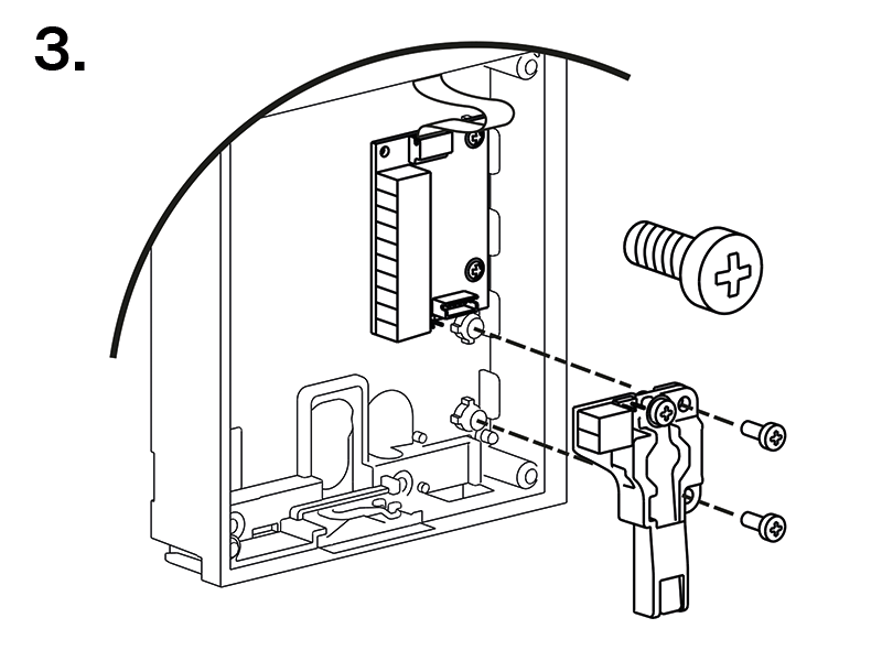
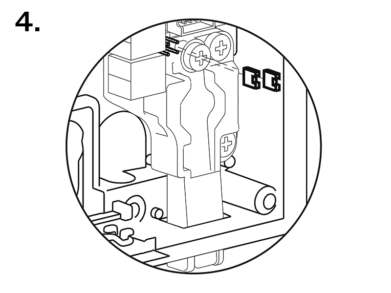
Tamper Switch Module
The Tamper Switch module (9155038, 01260-001) of 2N IP Style is used for securing the system against unauthorized tampering.
The tamper switch module is designed to protect an external module connected via VBUS. The 2N IP Style main unit has a tamper switch of its own.
Caution
Remember to purchase I/O Module, OSDP Module or Wiegand Module along with the Tamper Switch.
Features
The module contains two switches that open whenever the front frame is removed:
One switch leads directly to the terminal board and is designed for connection to an external security exchange (32 V DC / 50 mA max).
The other switch, in combination with the I/O module, OSDP module or Wiegand module, can be used for alarm triggering via the Automation interface in the 2N IP Style configuration.
Connectors and Installation
This module is not connected to the bus.
Jumpers are used for interconnecting the Tamper Switch pins with the I/O / OSDP / Wiegand module.
| |
 |  |
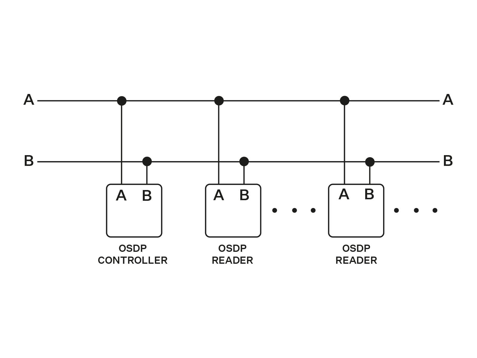
OSDP Module
The OSDP module (91550371, 02577-001) of 2N IP Style provides OSDP communication between a connected OSDP device (control panel, door controller) and the device. The OSDP module provides secure sending of such access data as the access card ID or PIN code.
Features
The module contains two bus connectors for the 2N IP Style bus.
These two connectors are fully interchangeable and can be used either as inputs from the main unit or outputs to other modules.
If this module is the last one on the bus, one of the connectors remains unconnected.
The module package includes a 80 mm long interconnecting cable.
The module also includes:
Isolated OSDP bus
Power and pairing mode signaling LED
Tamper Switch (9155038, 01260-001) input
Connectors and Installation
All the inputs and outputs are galvanically isolated from 2N IP Style with the insulation strength of 1500 V DC.
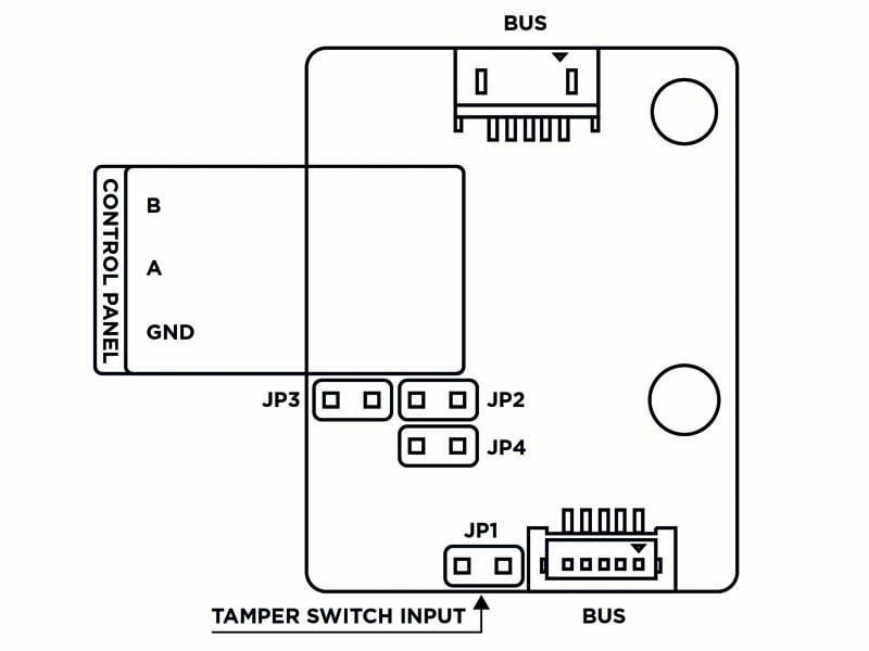
BUS | VBUS connectors for the bus connection |
Control Panel: A, B GND | |
JP1/2/3/4 | Jumpers 1/2/3/4 |
TAMPER | Tamper Switch (9155038, 01260-001) input |
The module is installed under another module, i.e. needs no separate position.
Having connected the OSDP module to 2N IP Style via the VBUS, connect the OSDP device to the module. The OSDP module uses the RS-485 bus for the interface.
Connect the OSDP device as instructed (A to B or B to A) keeping the correct order to avoid malfunction.
Caution
Mounting jumpers JP2 and JP3 results in a connection of strong pull-up/pull-down resistors (560 ohms) to the RS-485 bus. These jumpers must be mounted/unmounted together, i.e. one jumper cannot be mounted alone. Strong pull-up and pull-down resistors can be connected only and exclusively to one arbitrary device on the OSDP bus.
Mounting JP4 results in a connection of the terminating 120 ohm resistor between wires A and B of the OSDP bus. The terminating resistors may be connected exclusively on the first and last modules on the OSDP bus. We recommend the connection of these resistors on the first and last modules.
| |
Connection Recommendations

Configuration
Having logged in to the device web interface, use the menu to set the following:
Name the module for user identification (optional).
Choose a group for access data resending, making sure that the settings are identical with those of the access readers from which the data are to be resent (card ID, PIN).
The setting of the codes to be transmitted is optional.
Enter the OSDP address between 0 and 126 to set the OSDP module address on the OSDP line.
Set the communication rate in accordance with the requirements of the device to be connected.
Enter your own encryption key into 2N IP Style and the opponent’s device to ensure encrypted communication.
Enable forced encryption just for encrypted communication.
Any unencrypted communication from the OSDP device will be rejected if forced encryption is enabled.
If the OSDP device enables remote encryption key setting on a peripheral, you can use the installation mode. Once the encryption key is received, the common mode is automatically switched on. The installation mode is signaled by a LED fast flashing on the OSDP module.
Induction Loop Module
The Induction Loop module (9155041, 01263-001) on 2N IP Style is used for transmitting audio signals via the magnetic field directly into the hearing aids.
Features
The module contains two bus connectors for the 2N IP Style bus.
These two connectors are fully interchangeable and can be used either as inputs from the main unit or outputs to other modules.
If this module is the last one on the bus, one of the connectors remains unconnected.
The module package includes a 220 mm long interconnecting cable.
Specification
Used mode | T |
Maximum power | 2 W |
Frequency range | 100 Hz – 5 kHz / ± 3 dB |
Antenna output short circuit resistance | without restriction |