2N SmartCom ( further only abbreviated SmC ) test server location:
Public IP address test-m2m.2n.cz or 90.182.112.38
Listening port 1561
-
Install 2N SmartCom control panel, which will let you connect with 2N SmC server. www.2n.com
For the access data (login, password) please contact your salesman or send a request go to https://support.2n.com
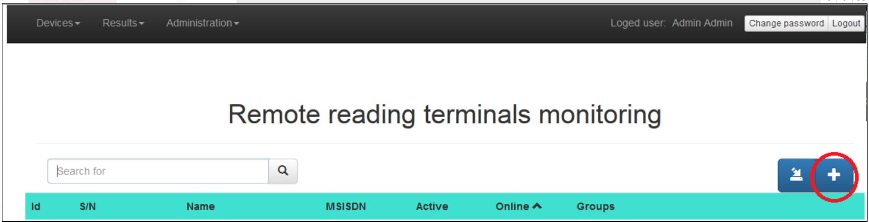
Then run web browser, insert test-m2m.2n.cz and fill your logging parameters (login, password). Press "plus" button for add 2N SmartCom terminal.
Fill all requested parameters and save with "OK" button.
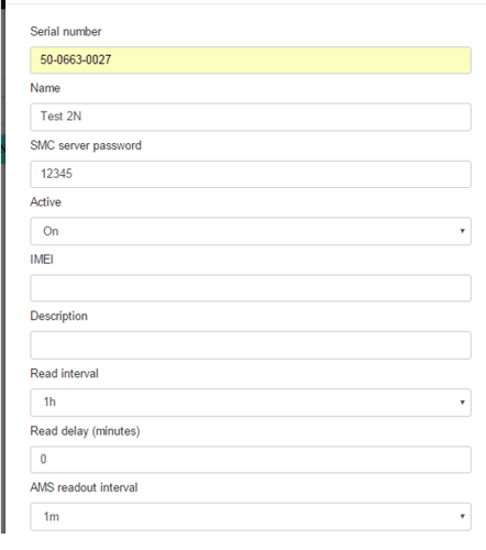
Serial number – serial number of 2NSmartCom PRO terminal
Name – user assigned name of 2N SmartCom PRO terminals
Active - 2N SmartCom PRO terminals status change (ON/OFF)
IMEI - International Mobile Equipment Identity
Description – the description assigned to the 2N SmartCom PRO terminal by the user
Read Interval – the interval used for the data transfer from the 2N SmartCom PRO terminal to the server. Example of 1h means the transfer is planned / performed exactly when the first sharp hour is reached and then every 60minutes
Read delay (minutes) – defines the time delay of the Read Interval from sharp hour. Can be used in case to be sure the 2N SmartCom PRO terminal already get all the data from all the connected meters
AMS Readout interval - the interval used for the data readout by the 2N SmartCom PRO terminal from the connected meters. Example of 1h means the transfer is planned / performed exactly when the first sharp hour is reached and then every 60minutes
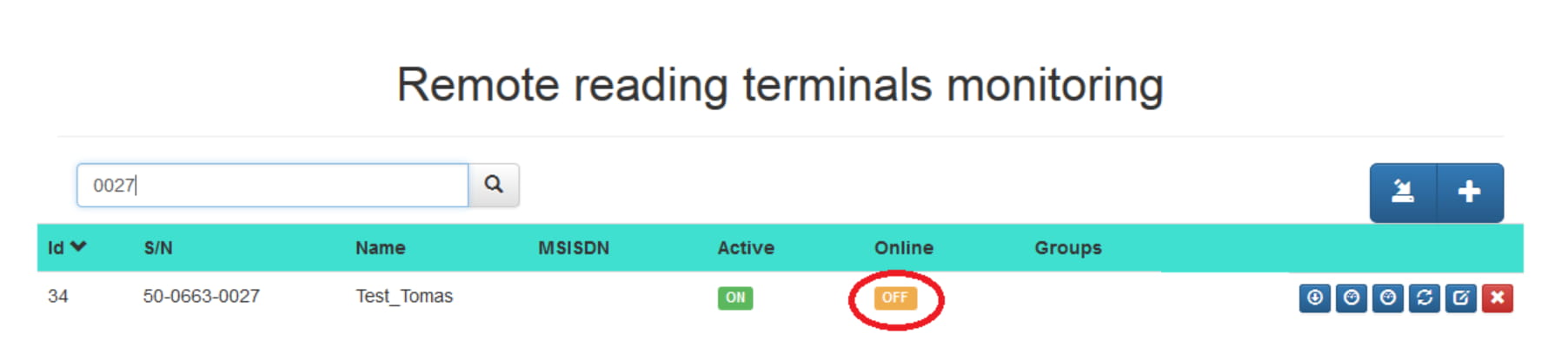
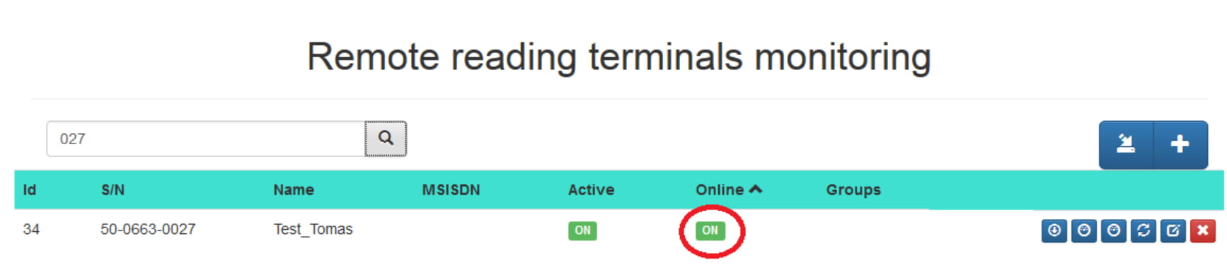
Your 2N SmartCom is now in section "Terminals Monitoring". Unit is offline now.
Configure your 2N SmartCom unit. You can use software 2N Terminal config or AT commands via hyperterminal (eg. putty)
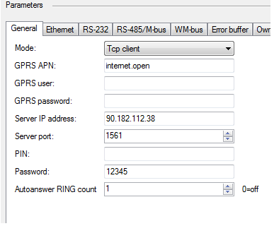
Mode: TCP Client
GPRS APN: APN used for the GPRS/UMTS connectivity access
GPRS user: GPRS User used for the GPRS/UMTS connectivity access
GPRS password: Password for the GPRS User used for the GPRS/UMTS connectivity access
Server IP address: 2N SmartCom server IP address where the 2N SmartCom PRO terminal is connecting
Server port: 2N SmartCom server port where the 2N SmartCom PRO terminal is connecting
PIN: SIM card PIN code
Password: 2N SmartCom PRO terminal password used for SMS configuration and 2N SmartCom server authorization
Press "Save and restart" buttont and your 2N SmartCom will connect to 2N SmC server.
Refresh your web browser by "F5". Unit is online and connected to 2N SmC server
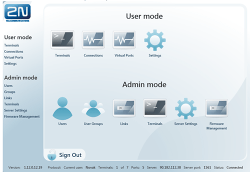
Then run 2N SmartCom control panel, fill in the generated Login and Password, Server Address 90.182.112.38 or test-m2m.2n.cz, Port 1561
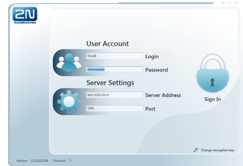
Confirm "Sign In"
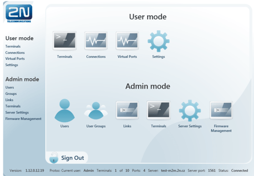
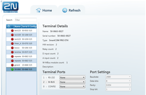
In the page "Terminals", you can also set parameters of RS232/RS485,MBUS
M - Bus data readout with 2N SmC server
If you use 2N SmartCOM PRO supporting AMS function, then 2N SmC server with web interface can readout units and parse M-Bus messages.
With special FW you can simply detect M-Bus meters by SMS
The easies is use firmware (SCE_1-12-0-12-252). Performing this command deletes all the data from 2N SmartCom PRO terminal memory as well as the meter reading configuration part. All the connected meters during the SMS processing will be available for the readout. The parameter interval is global for all installed meter by SMS.
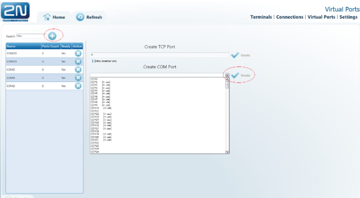
How to use Virtual ports
After successful connection is the next important step to install null-modem emulator com0com. You can install it in the sheet "Settings" in section "User mode"
In the tab "Virtual ports" add by button PLUS new virtual ports and confirm all by "Create"
In the tab "Terminals" in section "User mode" you can choose COM port. Further you can set parameters RS232/RS485

In the tab "Connections" you can download the data by pressing "Start".

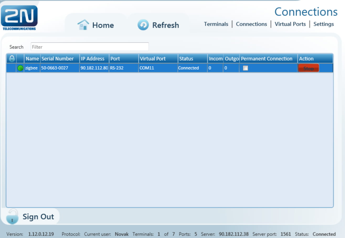
Right now, you have successfully set that data will be transfered to the COM11 port of your PC. You have to set up further details in your application. After that is the application able to read the data, example