Connectors 2N Sentrio Cabin
Connector | Connector name | Description |
|---|---|---|
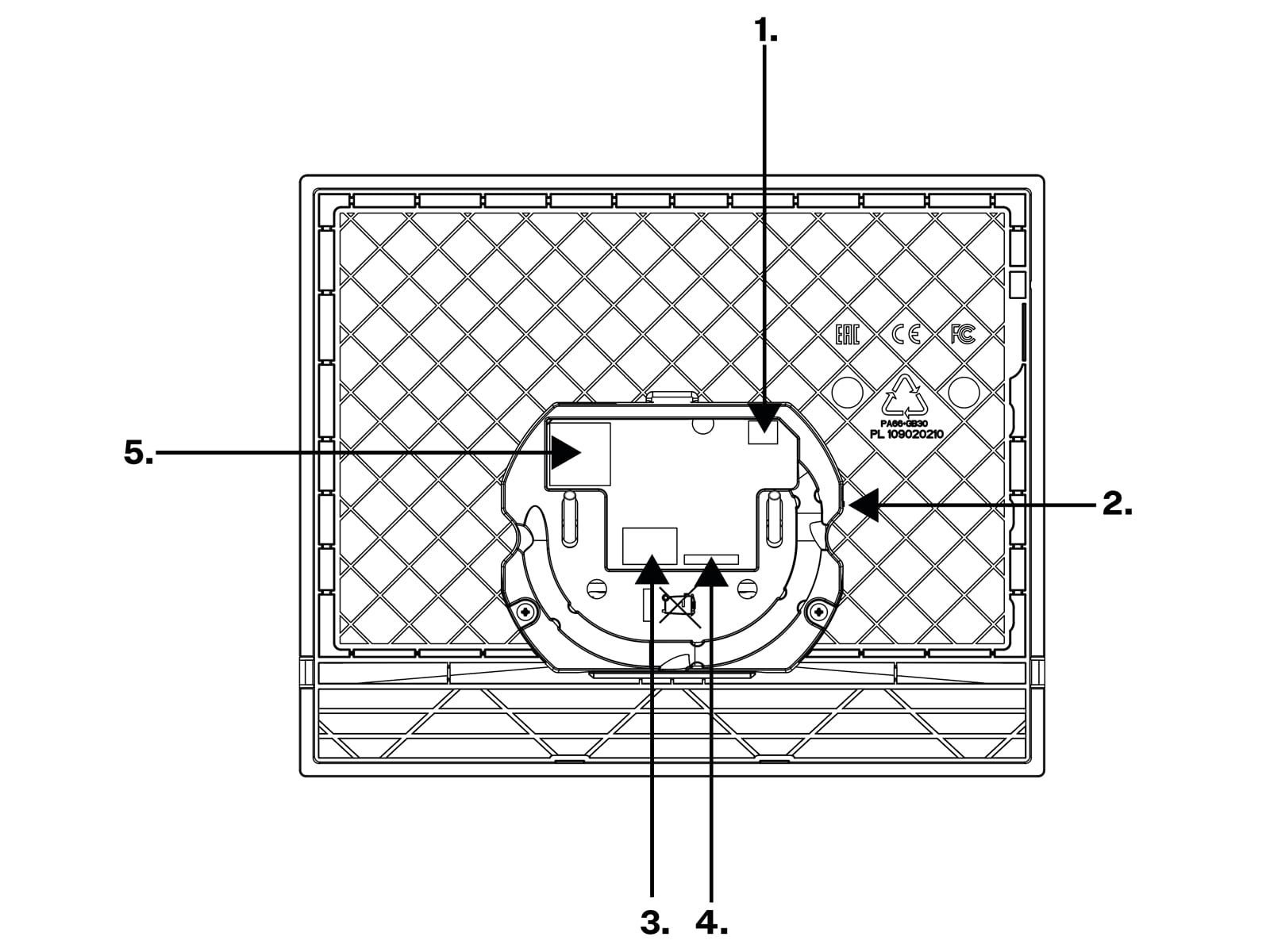
1 | Induction loop | External induction loop output. |
2 | RESET Button | The RESET button helps you restore the factory default values and restart the device. |
3 | Left-hand connector pair – external power supply input | External adapter (10–15 V DC) input connector. The left contact has a negative polarity (–), the right contact has a positive polarity (+). |
Right-hand connector pair – ALARM2 button | The doorbell button input is used as ALARM2 if the switch is used – accessible only to the operators for alarm call cancellation. CautionIf the switch is not connected to 2N Sentrio, this connector works as ALARM1 and has to be connected to the elevator cabin external button. Press the button for the predefined period of time to start emergency communication – the alarm call. | |
4 | 2N Sentrio Switch | 2N Sentrio Switch – main unit interconnection input For the full functionality, the main unit – switch interconnection must be made before the main unit is connected to the power supply from an external source or an Ethernet cable if PoE supply is selected. The switch is interconnected with the 2N Sentrio Cabin main unit with a 20 cm long eight-wire cable. The main unit feeds the switch using this cable. The main unit does not support more inputs, switch connectors 5–8 helps connect the inputs. |
5 | LAN Ethernet/PoE |