Device Connectors
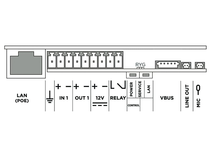
GROUND symbol | Grounding terminal CautionWe recommend that a grounding cable of the cross-section of 1.5 mm2 is used. |
LAN (PoE) | LAN connector (PoE 802.3af) |
IN1 | IN1 terminals for input in passive/ active mode (−30 V to +30 V DC)
|
OUT1 | OUT1 terminals of active input for Security Relay or electric lock connection: 8 up to 12 V DC depending on power supply (PoE: 10 V; adapter: source voltage minus 2 V), up to 600 mA |
12 V | External power supply terminals LPS/PS2 rated, 12 V ±15 % / 3 A DC |
RELAY | RELAY1 terminals with accessible 30 V / 1 A AC/DC NO contact. |
POWER/SERVICE/LAN | LED indicators (red/green/yellow). |
CONTROL | Hardware Configuration Button |
BOOT | The buttons is used for advanced diagnostic operations but is irresponsive to common users. |
VBUS | VBUS connector |
LINE OUT | External induction loop output. LINE OUT (1 VRMS) connector, type JST SHR-02V-S |
MIC | Microphone (MIC) connector |