Device Connectors
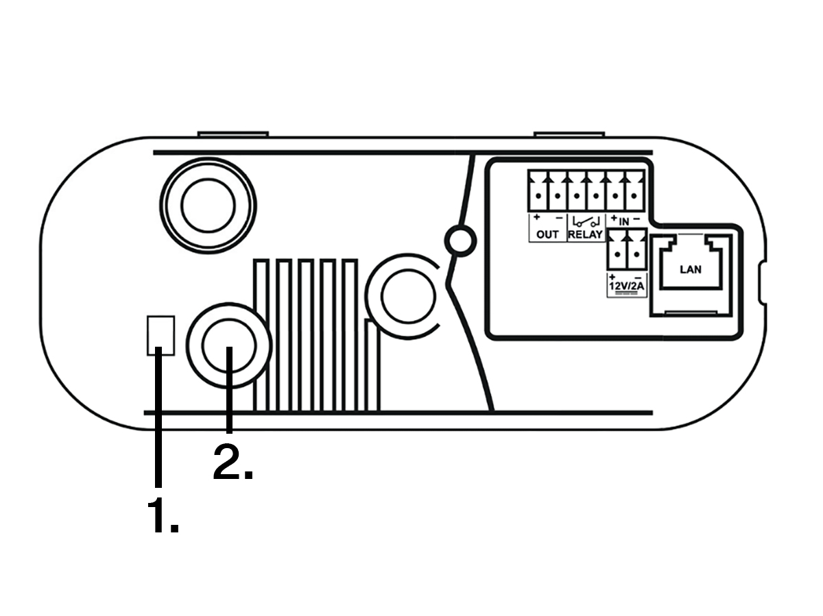
1. | LED Indicators |
2. | CONTROL button |
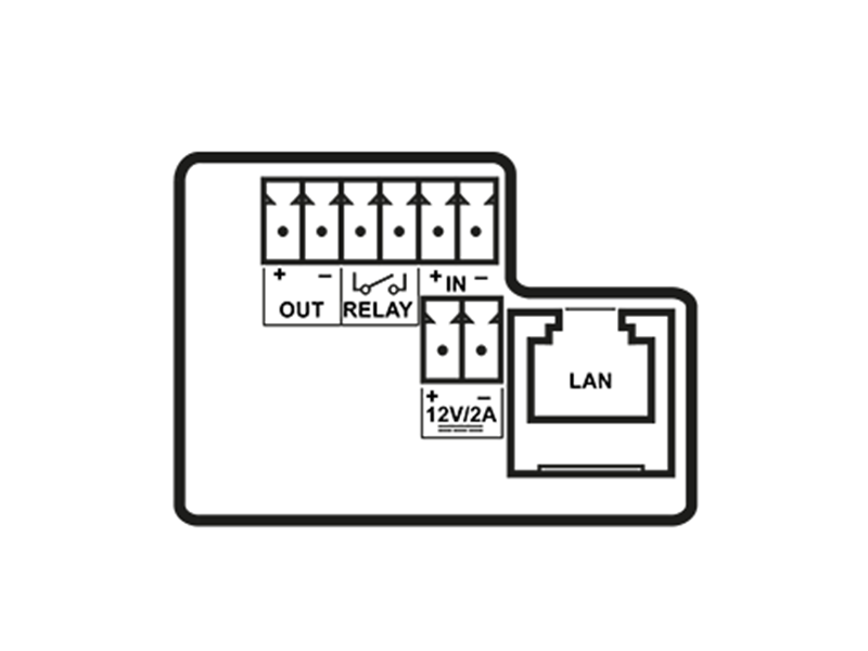
OUT | Active switch output: 12 V DC, max. 600 mA |
RELAY | RELAY terminals with accessible 30 V / 1 A AC/DC NO contact |
IN | IN1 terminals for input in passive / active mode (−30 V to +30 V DC)
|
12 V / 2 A | External power supply terminals 12 V ±15 % / 2 A DC |
LAN | LAN connector (PoE 802.3af) |
There are three main LED indicators on the IP One device:
– indicates power and system status.
– indicates the operating system (OS) and application statuses.
– indicates the network connection status. It flashes green at 100 Mbps and yellow at 10 Mbps.
Power LED | Status LED | Device Status |
|---|---|---|
RED | GREEN | Device ready (normal operation) |
DISABLED | YELLOW | Operating system starting up |
RED | DISABLED | Device switching on |
DISABLED | RED | Transient state on OS startup (if persistent, it means an error) |
DISABLED | GREEN | Transient state on OS startup (if persistent, it means an error) |
GREEN | DISABLED | Device error |
Note
The button is located on the back at the top of the device next to the LED indicators and is used for resetting the factory settings. Refer to Subs. ??? for details.