Installation and Configuration of Lift8 for Multiple Shafts
Description of the Lift8 CU, Audio Units and Modules is available in the link https://wiki.2n.com/l8um/latest/en/2-popis-a-instalace.
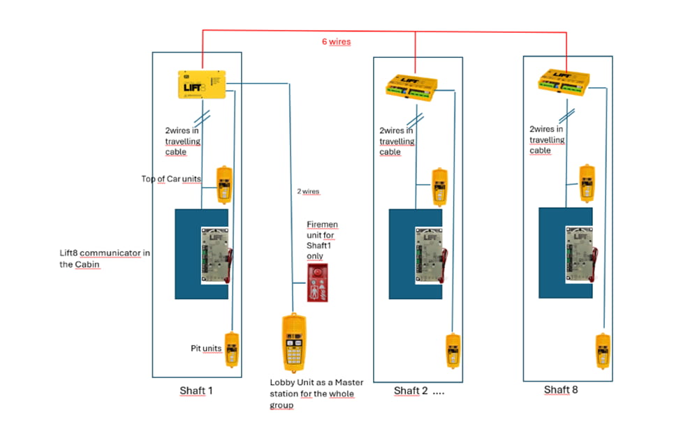
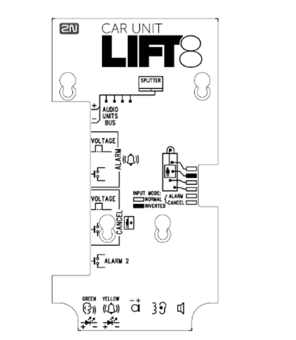
Target Schematic Diagram:
Preliminary Setup and Electrical System Installation:
Lift 8 Central Unit :
- Keep the CU disconnected from the mains.
- Loosen the three screws on the upper cover of the CU.
- Move the upper cover of the CU in such a way that you can remove it.
- Proceed with caution while removing the cover: be careful about the drain wire connecting the cover with the CU bottom part. Do not disconnect the wire unless there is a reason to do so!
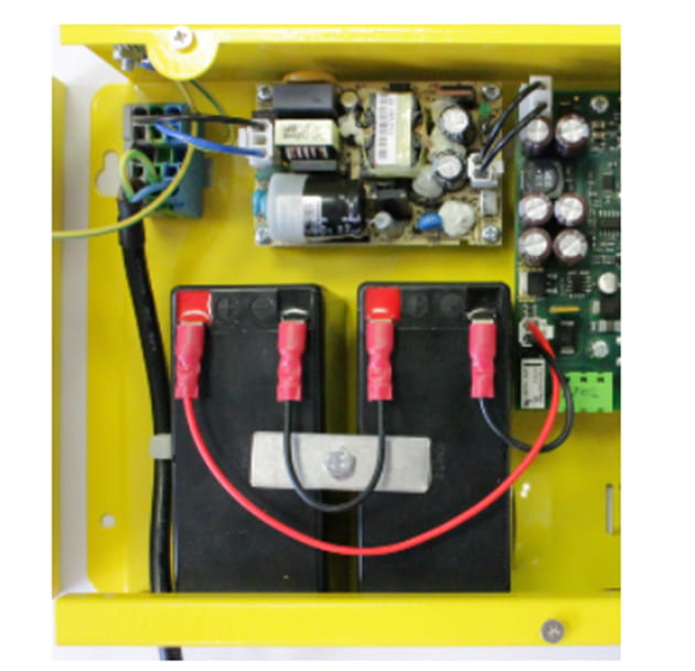
- Interconnect the rechargeable batteries, but do not connect them to the motherboard.
- Plug in the CU supply cable into a 230 V socket.
Now interconnect the batteries with the motherboard using the FASTON cable (see the Fig. below). Maintain polarity.
Fireman Unit:
Use the Torx 20 spanner included in the delivery to loosen the 4 screws and remove the audio unit's front cover. Find the board with electronics under the cover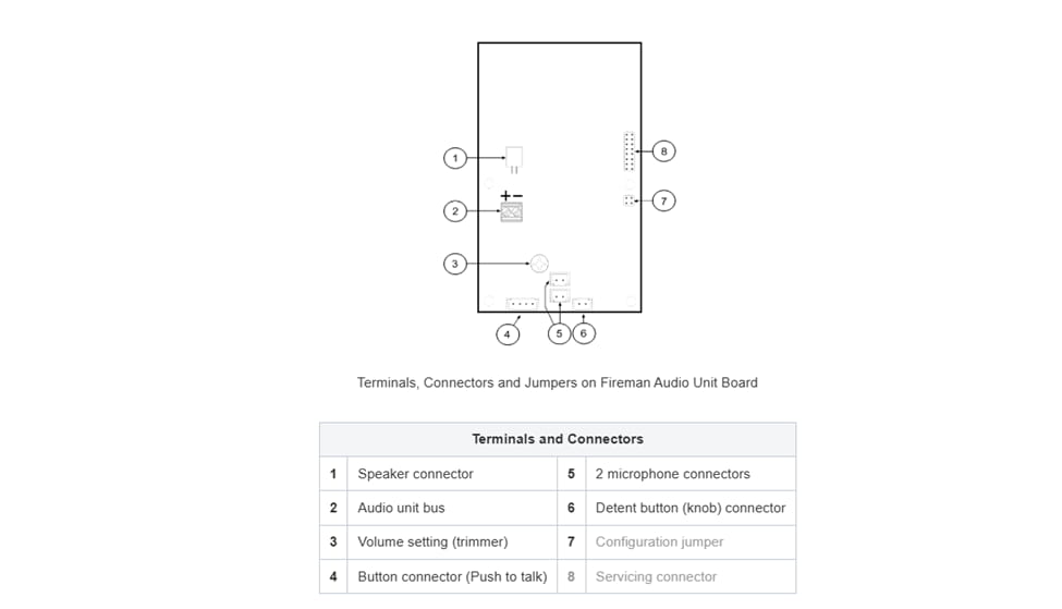
Remove the audio unit cover and unplug terminal 2 (audio unit bus). Connect the bus and replace the terminal keeping polarity.
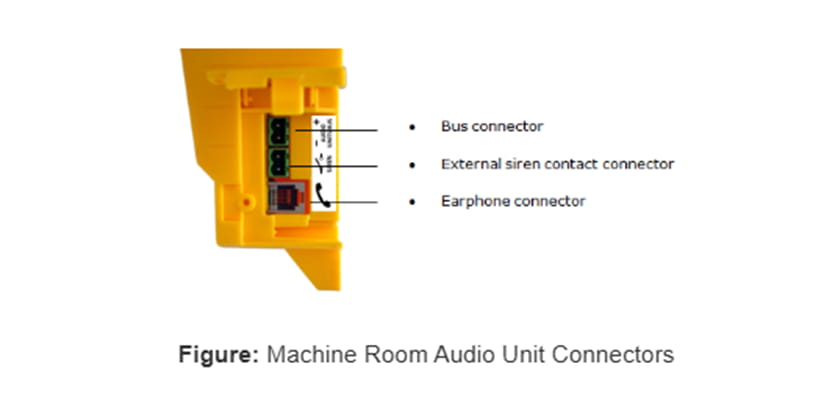
Machine Room:
Loosen the screws to the right and open the connector cover. There is just one connector under the cover: a bus connector. Pull out the terminal from the connector, connect the wires, and replace the terminal. Make sure that the polarity is maintained.
| In our test case, there are 3 shafts and MRU as a Lobby unit for all lifts in the group place. |
Address Configuration of MRU:
There is a group of jumpers under the transparent front cover. Do not use any of them if the machine room is only intended for the given lift. The audio unit identifies itself as the machine room for the given lift. If the machine room is to be shared by multiple lifts, configure the corresponding pins 1–8 for the lifts to share the machine room (numbered 1–8 from left to right 1–8).
Audio Unit Cop:
- Reconfigure the jumper on configuration jumper 12.
- If there is poor access to the pins, you can remove the electronics cover. Slightly loosen the four screws and shift the cover downwards. Now you can remove the cover.
- The first 4 pins help set the audio unit location (1 – cabin ceiling, 2 – cabin, default, 3 – under cabin, 4 – shaft bottom, 1+ 4 – cabin 2 roof, 2+ 4 – cabin 2, 3 + 4 under cabin 2). Use the jumpers for 1–4 settings. In the cabin 2 setting, set one jumper to the shaft bottom position (4) and then select the position with the other jumper (1 – cabin 2 roof, 2 – cabin 2, 3 – under cabin 2).
- Configure the required changes as printed on the electronics cover.
- If you have removed the cover, put it back in the original position and tighten the screw.
Pull the terminal out of connector 1 – Audio units bus, connect the bus audio units wires and replace the terminal to connector 1. Mind the polarity.
Audio Unit Shaft :
- Loosen the screws on the jumper-protecting door and open the door.
- Set the audio unit location. See the printed label under the door for the one-cabin configuration. To set the cabin 2 audio unit, insert the jumper to the shaft bottom position (left jumper) and then select the audio unit position with the other jumper (cabin 2 roof, cabin 2, under cabin 2).
- Close the door and tighten the screw.
| Jumper Configuration is Important to use the shaft unit as the top car unit and Pit Units ! |
Splitter
Remove the push-in terminal board from the main bus connector and connect six wires from the CU maintaining the polarity (power + -, audio + -, data + -). See the printed figure on the splitter cover.
Bus Connection between Audio Units and Splitter Interconnect the splitter and audio units using a two-wire bus maintaining polarity.
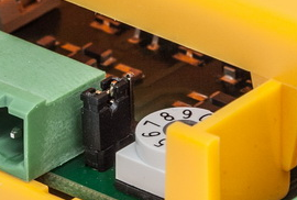
Address Configuration
Configure the splitter address for the given lift using a 10-position switch 0–9 (see the figure).
Configure lift 2–8 as 2–8 (set the switch to position 5 for lift 5, e.g.).
Lift 8 service tool initialization: https://wiki.2n.com/l8um/latest/en/5-service-tool/5-1-instalace-a-prihlasovani
Lift 8 Service Tool:
If you use a USB cable for a CU connection, select the USB connection type. The screen will change and the login name and password will only be visible. Enter the correct values. Refer to the text below for the default values. Now connect the CU and click Connect. The 2N Lift8 Service Tool automatically finds the connected CU on the PC and starts downloading parameters and logs. Having completed the download, the 2N Lift8 Service Tool is ready for work.
|
After initializing all the jumpers in the machine room, shaft units, and splitters, the connected devices should be configured as illustrated in the following diagrams taken from the service tool.

Alarm Call Configuration.
