Wiegand interface - Function overview
Wiegand interface is a wiring standard for interconnecting readers and the access control system.
There are basically two scenarios which can be used on our devices:
- Accept the information from 3rd party readers (IN), then the 2N device is controlling the access.
- Forward the information to 3rd party access control system (OUT), which controls the access.
Prerequisites
- 3rd party reader (e.g. 2N 9159030 / 9159031) or access control system with Wiegand interface.

- 2N IP Intercom or 2N Access Unit with additional Wiegand interface.
Product name
Additional Wiegand interface
- 2N Access Unit
- 2N Access Unit 2.0
- 2N IP Verso
- 2N IP Verso 2.0
- 2N IP Style
Wiegand module (9155037)
- 2N IP Force
Card Reader (125kHz - 9151011 / 13.56MHz - 9151031, 9151031S)
- 2N IP Vario
Card Reader (125kHz - 9137430)
To use the interface, no additional license is required. However when using 2N Wiegand module (9155037) and a 3rd party controller,
Gold license is necessary to control our RFID reader LED state (green/red) by the automation function.
Installation and configuration
Wiegand module overview (9155037)

Connectors
|
Section |
Interface |
Description |
|
Reader |
W0 IN, W1 IN, GND1 |
Isolated 2-wire Wiegand IN |
|
LED OUT |
Isolated open LED OUT switched against GND1 on Wiegand IN side (up to 24 V / 50 mA) | |
|
Control Panel
|
+U IN |
+UIN (5 to 15 V DC) Wiegand OUT power supply input |
|
W0 OUT, W1 OUT, GND2 |
Isolated 2-wire Wiegand OUT | |
|
LED IN |
Isolated input for open LED IN, input activated by GND2 or +U IN | |
|
- |
Tamper |
Tamper switch (9155038) input |
|
- |
BUS |
Connection to the main unit or next modules |
Installation
- The module contains two BUS connectors to connect module to the main unit.
- The connectors are fully interchangeable and can be used both as inputs from the main unit and outputs to other modules. If this module is the last one on the bus, one of the connectors remains unconnected. The module package includes an 80 mm long interconnecting cable.
- Wiegand module doesn't fit into the 2N Access Unit or 2N IP Style cover. There are many possibilities how you can resolve it:
-
- If you are using flush mounting box (9155014), you can place Wiegand module in there.
There is free space in the box which can be used. - It is possible to use blind module (9155039) into which the Wiegand can be placed.
In this case you would need to use a 2-module frame for 2N Access Unit. - It is possible to place a Wiegand module into some box behind the device or in some other place,
however the length of the bus cable has to be max. 5 m.
- If you are using flush mounting box (9155014), you can place Wiegand module in there.
Configuration
- Go to 2N device web interface, section Hardware - Extenders and find the Wiegand module here.
- Based on the scenario it is necessary to set the module name for input/output specification
in the SetOutput and InputChanged/Output Changed objects in the Automation.- The input LED IN is addressed as follows: <module_name>.<input1>, e.g. module2.input1
- The input Tamper is addressed as follows: <module_name>.<tamper>, e.g. module2.tamper
- The output LED OUT is addressed as follows: <module_name>.<output1>, e.g. module2.output1.
- Choose the right direction of the information flow (parameter Door) for the Attendance system purposes.

- If needed, there are also another parameters available:
-
Associated Switch
Set the switch to be activated after user authentication via this module. If you set Door Lock Switch, the authentication rules specified in Hardware - Digital Inputs - Door will be used. -
Received Code Format
Set the format for the codes to be received (Wiegand 26, 32, 37 and RAW). -
Output Wiegand Group
Assign the output Wiegand to a group to which the codes from the connected card readers or Wiegand inputs can be resent. -
Transmitted Code Format
Set the format for the codes to be transmitted (26-bit, 32-bit, 37-bit and RAW format, 35-bit, Corp. 1000, 48-bit, Corp. 1000 and Auto). -
Change Facility Code
Set the first code part via Wiegand. This applies to Wiegand OUT for 26-bit code format. Contact your security system supplier to know if the Facility Code is requested. -
Facility Code
Define the 2N IP device location in the security system. Enter a decimal value for the location (0–255).
-
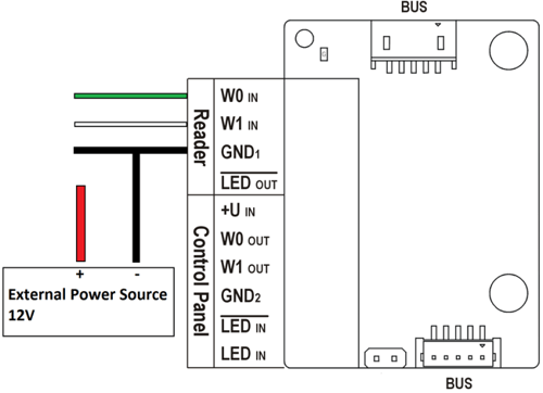
Connecting an external reader to the 2N Wiegand module
- Connect the external reader according to picture below. Red wire is connected to external power supply.
If your reader is not powered by default, you can use external supply (12 V / 2 A DC) terminal of the 2N device.
How does "LED OUT" work?
- The output is connected with LED IN on the 3rd party RFID reader to show the valid card state on the reader when swiping. It gives about 0.6V when activated.
- From the 2N device point of view, it acts as an additional output for automation purposes, where you can use block SetOutput with this parameter <module_name>.<output1> when the valid card is swiped.

Connecting the 2N Wiegand module to 3rd party access control system
- This side of the module has to be powered by the external power supply.

How does "LED IN" work?
- The input is connected with LED OUT on the 3rd party access control system to show the valid card state on our reader when swiping. From the 2N device point of view, it acts as an additional input for automation purposes, where you can use block InputChanged with this parameter<module_name>.<input1>
- There are two such inputs: LED IN (negated) - One cable is connected to LED IN (negated) and the other to GND2. LED IN - One cable is connected to LED IN (negated) and the other to +U. You cannot control this in Automation.

The 3rd party system typically sends a signal only if the card is valid. If you would like to show both green (valid) and red (invalid) LED states on the readers, you can use this automation function below.
For upon swiping a card and receiving a signal from the 3rd party controller to LED IN(negated) the device will produce sound and show the green (valid) LED, but if the device does not receive any signal back after reading the card and sending it via Wiegand the 2N device will play the denied sound and show red (invalid) LED.

Two 2N devices connected over Wiegand (to demonstrate the scenarios)
- In our example, 2N IP Verso acts like a 3rd party system with all the users and 2N Access Unit 2.0 is the reader.

- In automation for 2N IP Verso upon event UserAuthorized the LED OUT is activated and sends a signal to 2N Access Unit 2.0 to acknowledge that the card was accepted and is valid.
- In automation for 2N Access Unit 2.0 upon receiving a signal from 2N IP Verso to LED IN(negated) the 2N Access Unit 2.0 will produce access sound and show a green colour.
Connecting an external Wiegand reader to 2N IP Force
- Connect the external card reader to the Wiegand interface on the 2N IP Force card reader according to pictures below.
Red wire is connected to signalization bus providing card reader with +12 V power. If you use external power supply, you do not have to connect this cable.

Configuration
- Go to 2N IP Force web interface, section Hardware - Card Reader - Wiegand Interface.
- Based on the scenario set the Interface Mode for input (connect external reader) or output (to be connected to the 3rd party access control system)
- Choose the right direction of the information flow (parameter Door) for the Attendance system purposes.
- Setup the proper Received or Transmitted Code Format.

Connecting an external Wiegand reader to 2N IP Vario
- Connect the external card reader to the Wiegand interface on the 2N IP Vario card reader according to pictures below.
Red wire is connected to signalization bus providing card reader with +12 V power. If you use external power supply, you do not have to connect this cable.


Configuration
- Go to 2N IP Vario web interface, section Hardware - Card Reader - Wiegand Interface.
- Based on the scenario set the Interface Mode for input (connect external reader) or output (to be connected to the 3rd party access control system.
- Choose the right direction of the information flow (parameter Door) for the Attendance system purposes.
- Setup the proper Received or Transmitted Code Format.