Lift 8 Configuration for Multiple Shafts
Description of the Lift8 CU, Audio Units, and Modules is available in the link https://wiki.2n.com/l8um/latest/en/2-popis-a-instalace.
Target Schematic Diagram:

Preliminary Setup and Electrical System Installation:
Lift 8 Central Unit:
Installation:
Mount the Lift8 Central Unit firmly to a wall or cabinet where the power cable can reach 240v outlet. Mount the Lift Audio unit appropriately on the lift car C.O.P. and fix the Fireman’s Unit in the architrave alongside the designated Fireman’s lift landing doors at the FSAL level. Lift8 uses 2-wire bus technology and so two wires must be dedicated in the traveling cables to connect the lift car audio unit and similarly two wires (not supplied) must be run down from the Lift8 Central Unit to the FSAL to connect the Fireman’s audio unit, and finally the machine room audio unit should be connected via 2-wires (not supplied) to the Lift 8 Central unit as follows: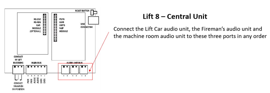
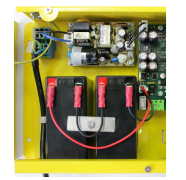
Rechargeable Battery Connection and State Check:
- Keep the CU disconnected from the mains
- Loosen the three screws on the upper cover of the CU.
- Move the upper cover of the CU in such a way that you can remove it.
- Proceed with caution while removing the cover: be careful about the drain wire connecting the cover with the CU bottom part. Do not disconnect the wire unless there is a reason to do so!
- Interconnect the rechargeable batteries, but do not connect them to the motherboard.
- Plug the CU supply cable into a 230 V socket.
- Now interconnect the batteries with the motherboard using the FASTON cable (see Fig. below). Maintain polarity.
Fireman Unit:
Use the Torx 20 spanner included in the delivery to loosen the 4 screws and remove the audio unit's front cover. Find the board with electronics under the cover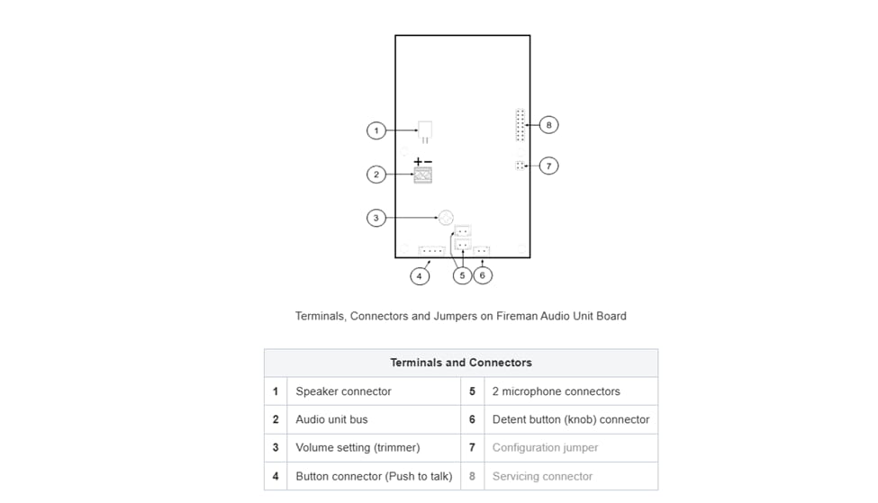
Remove the audio unit cover and unplug terminal 2 (audio unit bus). Connect the bus and replace the terminal keeping polarity.
The default function of the Fireman unit is to provide a priority call function exclusively for the shaft in which it is installed.
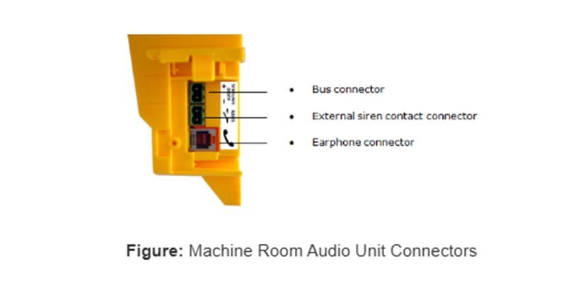
Machine Room:
Loosen the screws to the right and open the connector cover. There is just one connector under the cover: a bus connector. Pull out the terminal from the connector, connect the wires and replace the terminal. Make sure that the polarity is maintained.
In our case, there are 3 shafts and to use MRU as a Lobby unit for all lifts in the group place. Please follow the following steps to attain it:
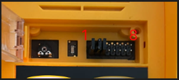
Address Configuration of MRU:
There is a group of jumpers under the transparent front cover. Do not use any of them if the machine room is only intended for the given lift. The audio unit identifies itself as the machine room for the given lift. If the machine room is to be shared by multiple lifts, configure the corresponding pins 1–8 for the lifts to share the machine room (numbered 1–8 from left to right 1–8).
Audio Unit Cop:
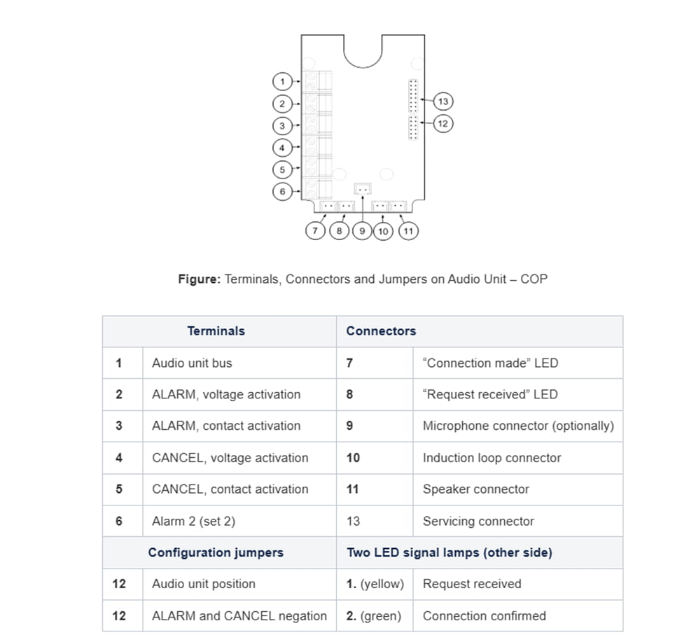
- Reconfigure the jumper on configuration jumper 12.
- If there is poor access to the pins, you can remove the electronics cover. Slightly loosen the four screws and shift the cover downwards. Now you can remove the cover.
- The first 4 pins help set the audio unit location (1 – cabin ceiling, 2 – cabin, default, 3 – under cabin, 4 – shaft bottom, 1+ 4 – cabin 2 roof, 2+ 4 – cabin 2, 3 + 4 under cabin 2). Use the jumpers for 1–4 settings. In cabin 2 setting, set one jumper to the shaft bottom position (4) and then select the position with the other jumper (1 – cabin 2 roof, 2 – cabin 2, 3 – under cabin 2).
- Configure the required changes as printed on the electronics cover.
- If you have removed the cover, put it back in the original position and tighten the screw.
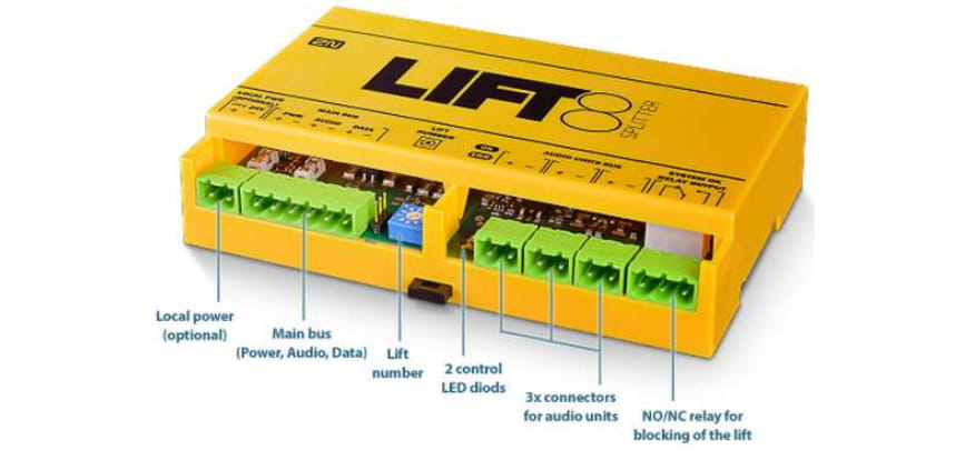
Remove the push-in terminal board from the main bus connector and connect six wires from the CU maintaining the polarity (power + -, audio + -, data + -). See the printed figure on the splitter cover.
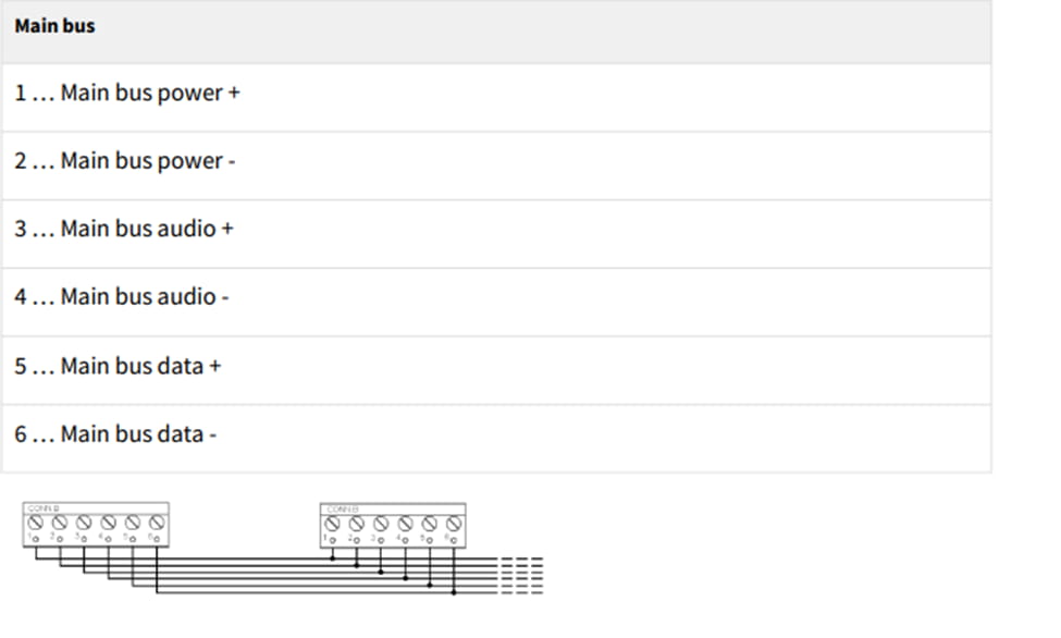
Bus Connection between Audio Units and Splitter Interconnect the splitter and audio units using a two-wire bus maintaining polarity.
Address Configuration
Configure the splitter address for the given lift using a 10-position switch 0–9 (see the figure).
Configure lift 2–8 as 2–8 (set the switch to position 5 for lift 5, e.g.).
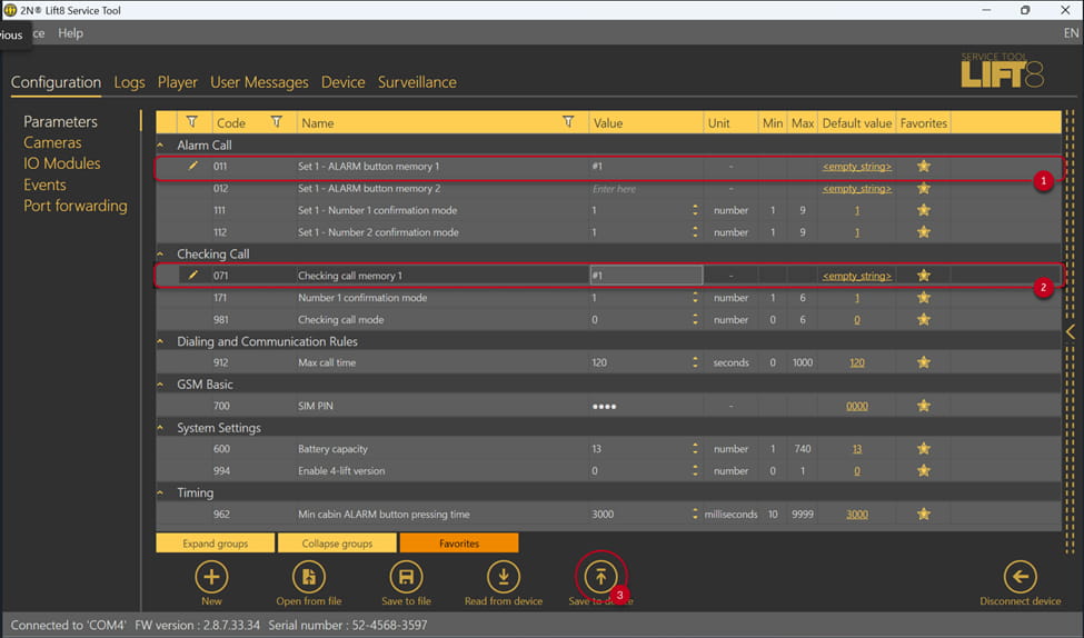
The next step after interconnecting all the devices physically in the desired position next step is Configuring the Alarm Calls.
Lift 8 service tool initialization: https://wiki.2n.com/l8um/latest/en/5-service-tool/5-1-instalace-a-prihlasovani
After initializing all the jumpers in the machine room, shaft units, and splitters, the connected devices should be configured as illustrated in the following diagrams taken from the service tool

Alarm Call Configuration (No Module) Internally :
ALARM parameter: "#" and the number (1–8) of the shaft in which the audio unit is located, e.g. "#1",