Wiegand interface Configuration in 2N Intercom
Wiegand overview
Wiegand interfaces is generally used for interconnecting peripherals such as external RFID card reader, finger print reader. iris recognition, etc. with any main unit in our case (in 2N IP Intercom).
Wiegand interfaces uses three wires in physical layer:
-
First wire is ground (GND)
-
Second is usually called Data0, Data low or D0
-
The last one is called Data1, Data high od D1.
When no data is sending, both Data wires is pull up tu high voltage - usually 5V.
When bit=0 is sending, the D0 is pulled to low voltage for a specific time and D1 stays on high.
On the other way when bit=1 has been send, then D1 is pulled to low voltage and D0 stays on high.
The longest possible distance connecting devices via this interface is usually about 150 m.
Wiegand protocol (Wiegand messages)
Wiegand messages are very often called Wiegand 26, because this massage is 26 bits long. It contains 8 bits of facility code and 16 bits of ID code.
The message starts with a parity bit calculated from first 12 bits and ends with the second partity bit that is calculated from last 12 bits.
Parity bits are calculated with reversal mutual logic. There are more Wiegand specifics protocol depending on the message length (Wiegand 32-bits, Wiegand 37-bits).
The Wiegand interfaces can be switched into Input or Output mode.
It Is possible to change the Message format. There are three predefined specification of Wiegand message:
-
26 bit
-
32 bit
-
37 bits
Or you can set it in a Raw mode.
Wiegand in 2N IP Force/Safety
Both internal RFID card readers (125kHz and 13.56 MHz) have one Wiegand interface (Part No. 9151011, 9151031/9151017, 9151031S/9151019).
There is a limited functionality in 2N IP Safety:
-
This extending module on 2N IP Safety with RFID Card reader cannot be used as an internal RFID Card reader in 2N IP Safety because of the metallic body without any plastic window possibility.
-
This module can be use only as the extending modul with Wiegand interface and additional input and ouputs that can be connected with some external facility.
In the 2N IP Force device you need to choose direction of the communication in the configuration web interface
-
You can find it under "Hardware" tab
-
Next select "Card Reader" (1) and then "Wiegand Interface" (2) and "Interface Mode" (3)

- Basic schematic of interconnecting 2N IP Force and some peripheral:

- Wiring example you can find in the picture below:

|
RED | DC +12V |
|
BLACK | GND |
|
GREEN | D0 |
|
WHITE | D1 |
|
BLUE | LED |
|
YELLOW | Buzzer |
Wiegand in 2N IP Vario
2N IP Vario needs internal RFID Card reader for connecting external facility via Wigand interface (Part No. 9137430E).
For 2N IP Vario connect the external card reader according the picture below.
Red wire is connected to signalization bus providing external card reader with +12 V power. If you use external power supply, you do not have to connect this cable.
- In the 2N IP Vario device you need to choose direction of the communication in the configuration web interface:Basic schematic of interconnecting In the 2N IP Vario and some peripheral:

Wiegand in 2N IP Verso/IP Verso 2.0
The Wiegand module (Part No. 9155037) is one of the 2N IP Verso system elements and is used for connecting an external Wiegand device (RFID card reader, fingerprint / biometric data scanner) and/or connecting the intercom to an external security exchange.
All the inputs and outputs are galvanically isolated from the intercom with the insulation strength of 500 V DC. It is necessary to feed +U IN on Wiegand OUT from the Control Panel.
- Reader – connects an external Wiegand-supporting reader. The reader sends information on the intercom card number.
- Control Panel – used for connection to the security PBX / access system to which the intercom sends the card number information.
- The module contains two 2N IP Verso bus connectors.
- These two connectors are fully interchangeable and can be used either as inputs from the basic unit or outputs to other modules.
- If this module is the last one on the bus, one of the connectors remains unconnected.
- The module package includes a 80 mm long interconnecting cable.
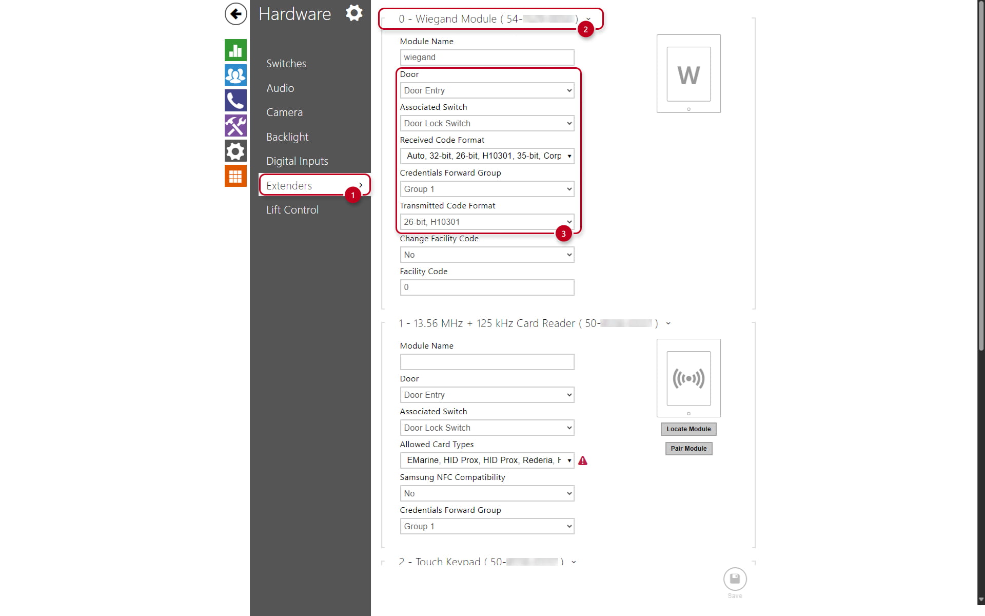
Configure the module name in the Module name parameter in the "Hardware":
-
Select "Extenders" (1)
-
Locate the "Wiegand Module" (2) and it's configuration (3)
-
The LED IN input is addressed as follows: <module_name>.<input1>, e.g. module2.input1.
-
The Tamper input is addressed as follows: <module_name>.<tamper>, e.g. module2.tamper.
-
The LED OUT output (negated) is addressed as follows: <module_name>.<output1>, e.g. module2.output1.

- Wiegand Module Overview:

- Recommended reader - bus driver wiring diagram:

- Recommended reader wiring diagram with OC output:

| Reader | W0 IN, W1 IN, GND1 | Isolated 2-wire WIEGAND IN |
| Reader | LED OUT | Isolated open LED OUT switched against GND1 on WIEGAND IN side (up to 24 V / 50 mA) |
| Control Panel | +U IN | +UIN (5 to 15 V DC) WIEGAND OUT power supply input |
| Control Panel | W0 OUT, W1 OUT, GND2 | Isolated 2-wire WIEGAND OUT |
| Control Panel | LED IN (negated) | Isolated input for open LED IN, input activated by GND |
| Control Panel | LED IN | Isolated input for open LED IN, input activated by +U |
| Control Panel | G | +U IN WIEGAND OUT active supply LED indicator |
| Control Panel | TAMPER | Tamper switch (Part No. 9155038) input |
Wiegand in 2N IP Style
The Wiegand module (Part No. 9155037) is one of the 2N IP Style system elements and is used for connecting an external Wiegand device (RFID card reader, fingerprint / biometric data scanner) and/or connecting the intercom to an external security exchange.
All the inputs and outputs are galvanically isolated from the intercom with the insulation strength of 500 V DC. It is necessary to feed +U IN on Wiegand OUT from the Control Panel.
- Reader – connects an external Wiegand-supporting reader. The reader sends information on the intercom card number.
- Control Panel – used for connection to the security PBX / access system to which the intercom sends the card number information.
- The module contains two 2N IP Style bus connectors.
- These two connectors are fully interchangeable and can be used either as inputs from the basic unit or outputs to other modules.
- If this module is the last one on the bus, one of the connectors remains unconnected.
- The module package includes a 80 mm long interconnecting cable.
Configure the module name in the Module name parameter in the "Hardware":
-
Select "Extenders" (1)
-
Locate the "Wiegand Module" (2) and it's configuration (3)
-
The LED IN input is addressed as follows: <module_name>.<input1>, e.g. module2.input1.
-
The Tamper input is addressed as follows: <module_name>.<tamper>, e.g. module2.tamper.
-
The LED OUT output (negated) is addressed as follows: <module_name>.<output1>, e.g. module2.output1.
- Wiegand Module Overview:

- Recommended reader - bus driver wiring diagram:

- Recommended reader wiring diagram with OC output:

- Pinout for Wiegand Module:
| Reader | W0 IN, W1 IN, GND1 | Isolated 2-wire WIEGAND IN |
| Reader | LED OUT | Isolated open LED OUT switched against GND1 on WIEGAND IN side (up to 24 V / 50 mA) |
| Control Panel | +U IN | +UIN (5 to 15 V DC) WIEGAND OUT power supply input |
| Control Panel | W0 OUT, W1 OUT, GND2 | Isolated 2-wire WIEGAND OUT |
| Control Panel | LED IN (negated) | Isolated input for open LED IN, input activated by GND |
| Control Panel | LED IN | Isolated input for open LED IN, input activated by +U |
| Control Panel | G | +U IN WIEGAND OUT active supply LED indicator |
| Control Panel | TAMPER | Tamper switch (Part No. 9155038) input. Note - Tamper switch has been integrated into the rear panel of the IP Style unit. |
2N IP Wiegand Isolator
The 2N IP Wiegand Isolator (Part No. 9159011) is used for galvanic isolation of the Wiegand bus.
- This device can prevent communication error and protect both communicating device:
